Cryptographic operations
In this section we describe the AIR constraints for Miden VM cryptographic operations.
Cryptographic operations in Miden VM are supported by the hash, memory, bitwise, and ACE chiplets. The Core AIR removes each typed request from the relevant LogUp relation with negative multiplicity; the AIR or component responsible for that relation adds the matching response with positive multiplicity.
Hasher interactions use typed, domain-separated LogUp messages. For message kind , controller address , node index , and payload , write
where is the fixed bus prefix for that semantic message kind. The separate prefixes domain-separate equal payloads except with the standard random-encoding collision probability.
COMPRESS
The COMPRESS operation applies one Eidos compression to the top 12 stack elements, arranged as
[BLOCK_LO, BLOCK_HI, CV]. The 8-element message block is preserved and the 4-element chaining
value is replaced with the updated chaining value:
Before: [BLOCK_LO, BLOCK_HI, CV,  ...]
After:  [BLOCK_LO, BLOCK_HI, CV', ...]
The prover supplies the hasher-controller row address in helper register . The controller row commits the input state and returned chaining value to one physical 32-row block in the standalone Eidos compression AIR. The decoder removes both typed messages from the chiplet bus.
For COMPRESS, define the input and output values as follows:
The one-row controller overlays its input and output at the same address; the compression AIR enforces the 32-row computation behind that controller row.
The Core row removes both messages with multiplicity . Matching positive messages from the hasher controller bind the input state and returned chaining value to a valid Eidos compression.
The effect of this operation on the rest of the stack is:
- No change in positions through and from position onward.
MPVERIFY
The MPVERIFY operation verifies that a Merkle path from the specified node resolves to the specified root. This operation can be used to prove that the prover knows a path in the specified Merkle tree which starts with the specified node.
Prior to the operation, the stack is expected to be arranged as follows (from the top):
- Value of the node, 4 elements ( in the below image)
- Depth of the path, 1 element ( in the below image)
- Index of the node, 1 element ( in the below image)
- Root of the tree, 4 elements ( in the below image)
The Merkle path itself is expected to be provided by the prover non-deterministically (via the advice provider). If the prover is not able to provide the required path, the operation fails. Otherwise, the state of the stack does not change. The diagram below illustrates this graphically.
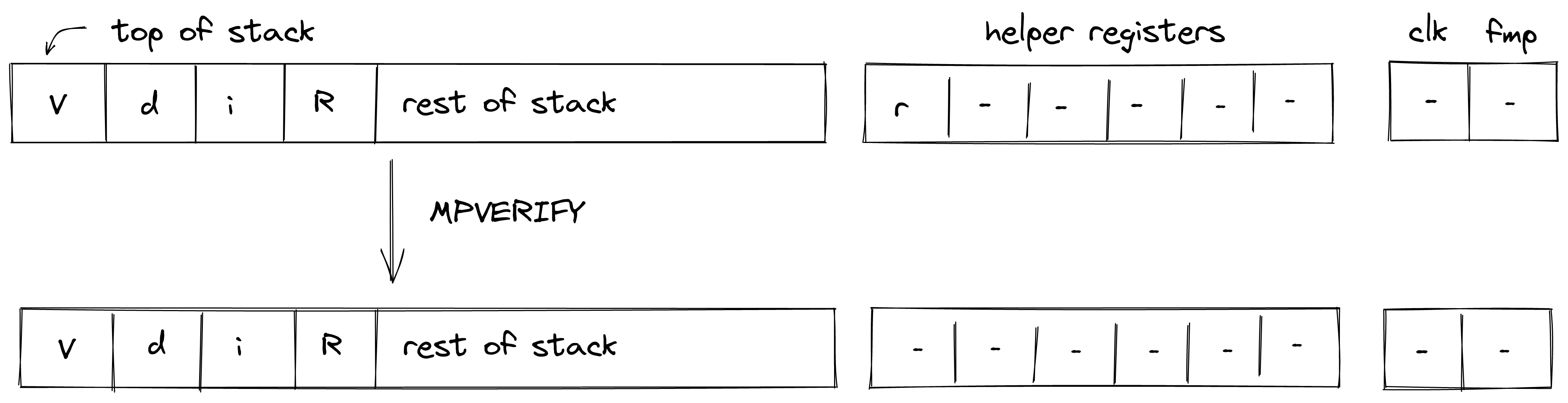
In the above, (located in helper register ) is the row address from the hash chiplet set by the prover non-deterministically. Helper register contains the first Merkle direction bit, denoted below.
For the MPVERIFY operation, we define input and output values as follows:
The input carries the leaf node and its Merkle index; the output carries the resulting root.
The Core row removes both messages with multiplicity . Matching controller messages enforce that the input and output rows are present and exactly rows apart, where is the depth of the node. Each Merkle level contributes one controller row; that row overlays its input and output messages.
The effect of this operation on the rest of the stack is:
- No change starting from position .
MRUPDATE
The MRUPDATE operation computes a new root of a Merkle tree where a node at the specified position is updated to the specified value.
The stack is expected to be arranged as follows (from the top):
- old value of the node, 4 element ( in the below image)
- depth of the node, 1 element ( in the below image)
- index of the node, 1 element ( in the below image)
- current root of the tree, 4 elements ( in the below image)
- new value of the node, 4 element ( in the below image)
The Merkle path for the node is expected to be provided by the prover non-deterministically (via merkle sets). At the end of the operation, the old node value is replaced with the new root value computed based on the provided path. Everything else on the stack remains the same. The diagram below illustrates this graphically.
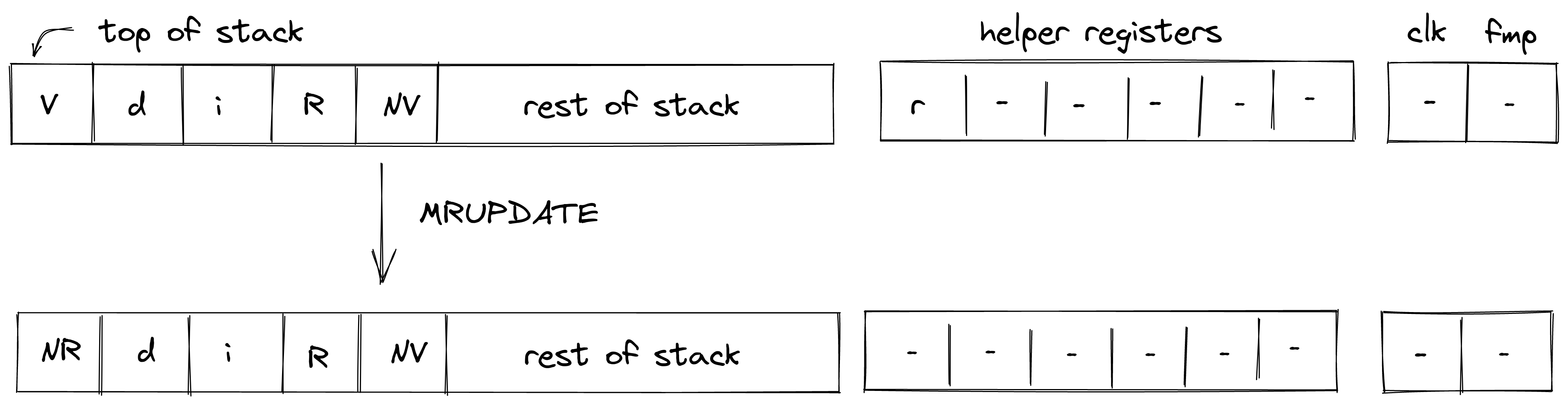
In the above, (located in helper register ) is the row address from the hash chiplet set by the prover non-deterministically. Helper register contains the first Merkle direction bit, denoted below.
For the MRUPDATE operation, we define input and output values as follows:
In the above, the first two expressions correspond to inputs and outputs for verifying the Merkle path between the old node value and the old tree root, while the last two expressions correspond to inputs and outputs for verifying the Merkle path between the new node value and the new tree root. The hash chiplet ensures the same set of sibling nodes are used in both of these computations.
The Core row removes all four messages with multiplicity . Matching controller messages enforce that the input and output rows for both node/root combinations are present. The old-path output is rows after the old-path input, the new-path input starts immediately after that at offset , and the new-path output is rows after the initial old-path input. This also ensures that the old computation is immediately followed by the new computation.
The effect of this operation on the rest of the stack is:
- No change for positions starting from .
Merkle range checks
MPVERIFY and MRUPDATE request 16-bit range checks for and
. Together, the checks accept exactly .
The path bits must also describe the canonical integer represented by the node-index field element. At each controller row, the hash controller enforces
where is a boolean direction bit. This is a field equality modulo . By itself, it does not distinguish an integer index from that index plus .
The stack/hasher lookup addresses bind the computation to exactly levels, and the controller
ends with . To prevent a wrapped 64-bit bit string from representing the same field
element, CoreAir uses the six decoder helpers
[addr, b, y0, y1, y2, y3]
on each MPVERIFY and MRUPDATE row. Here is the first direction bit and
For the stack node index , Core enforces to be boolean and constrains
The typed Merkle-init request carries . Its matching controller response derives the first bit
as , so the lookup binds the Core helper to the actual path direction. The RangeCheck
bus checks all four limbs and also checks . The limb checks give , and the
additional check gives , hence . Together with the equation and the
controller binding of , this rules out the non-canonical depth-64 alias.
All seven Merkle range requests are emitted from existing Core lookup columns:
- the stack-overflow column checks , , and for both operations;
- for
MPVERIFY, the chiplet-request column checks , while the block-stack/range/log-deferred column checks , , and ; - for
MRUPDATE, the block-stack/range/log-deferred column checks , , , and .
The execution tracer replays the corresponding requests into the fixed And8 range-table multiplicities. No canonical-index witness is stored in the native hash controller.
CRYPTOSTREAM
CRYPTOSTREAM encrypts two words from memory using one Eidos XOF counter block. Its stack
transition is
Before: [K_CTR(4), counter, src,   dst,    remaining, ...]
After:  [K_CTR(4), counter+1, src+8, dst+16, remaining-1, ...]
The Eidos compression input is [counter, 0, 0, 0, 0, 0, 0, 0, K_CTR]. The raw XOF result supplies sixteen
u32 keystream lanes. Each of the eight plaintext field elements is unpacked into low and high u32
limbs, XORed with the corresponding lanes byte by byte, and written as two field elements. This is
why eight input elements advance dst by sixteen elements.
The AIR binds three parts of the operation through typed LogUp relations:
- the core row supplies the clock-tagged Eidos XOF input consumed by the compression trace;
- two 8-row AEAD-stream trace entries prove the two four-element source reads and four two-element destination writes;
- the And8 lookup table proves every byte-level XOR used to form the expanded ciphertext limbs.
The core constraints preserve K_CTR and stack positions through , increment the counter
and pointers by their fixed amounts, and decrement remaining. Address validation requires
word-aligned, non-overlapping source and destination blocks.
FRIE2F4
The FRIE2F4 operation performs one factor-4 FRI layer fold over the quadratic extension field. It also checks consistency with the previous folded layer and writes the loop state consumed by the next FRI layer.
The stack for the operation is expected to be arranged as follows:
- The first stack elements contain opened leaf values to be folded. Each value is represented by two field elements. The leaf values are stored in bit-reversed order: , , , .
- The next element is the query position in the folded domain. It can be computed as , where is the position in the source domain, and is size of the folded domain.
- The next element is the natural coset index . Since the size of the source domain is always times bigger than the size of the folded domain, possible coset values are , , , and .
- The next element is a power of the current source-domain generator used to compute the domain point .
- The next two elements contain the result of the previous layer folding - a single element in the extension field denoted as .
- The next two elements specify a random verifier challenge for the current layer defined as .
- The last element on the top of the stack () is expected to be a memory address of the layer currently being folded.
The diagram below illustrates stack transition for FRIE2F4 operation.
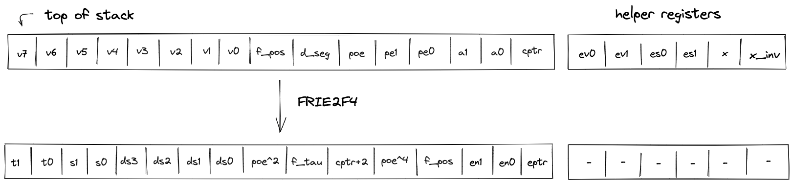
At the high-level, the operation does the following:
- Computes the domain value based on values of and the coset index.
- Using and , folds the query values into a single value .
- Compares the previously folded value to the leaf value selected by the coset index.
- Computes the new value of as (this is done in two steps to keep the constraint degree low).
- Increments the layer address pointer by .
- Shifts the stack by to the left. This moves an element from the stack overflow table into the last position on the stack top.
To keep the constraint degree low, the operation uses all helper registers and the first next-state stack elements as degree-reduction intermediates. Callers should treat those output elements as scratch.
TODO: add detailed constraint descriptions. See discussion here.
The effect on the rest of the stack is:
- Left shift starting from position .
HORNERBASE
The HORNERBASE operation performs steps of the Horner method for evaluating a polynomial with coefficients over the base field at a point in the quadratic extension field. More precisely, it performs the following updates to the accumulator on the stack:
where are the coefficients of the polynomial, the evaluation point, the current accumulator value, the updated accumulator value, and , are helper variables used for constraint degree reduction.
The stack for the operation is expected to be arranged as follows:
- The first stack elements (positions 0-7) are the base field elements representing the current 8-element batch of coefficients for the polynomial being evaluated, arranged as where is at position 0 (top of stack). Here is the highest-degree coefficient ( term) and is the constant term.
- The next stack elements are irrelevant for the operation and unaffected by it.
- The next stack element contains the word-aligned address
alpha_ptrpointing to the word , which contains the evaluation point . - The next stack elements contain the value of the current accumulator .
Execution fails if either padding element is nonzero; the AIR enforces the same requirement.
The diagram below illustrates the stack transition for HORNERBASE.

After calling the operation:
- Helper registers contain .
- Stack elements and contain the updated accumulator .
More specifically, the stack transition for this operation must satisfy the following constraints. Here is an element of with . We write , , , and for the extension-field coefficients.
HORNERBASE removes one typed MemoryReadWord message with payload
[ctx, s13, clk, h0, h1, 0, 0]. Matching it against the memory-chiplet response also constrains
the unused half of the word to zero:
The effect on the rest of the stack is:
- No change.
HORNEREXT
The HORNEREXT operation performs steps of the Horner method for evaluating a polynomial with coefficients over the quadratic extension field at a point in the quadratic extension field. More precisely, it performs the following update to the accumulator on the stack
where are the coefficients of the polynomial, the evaluation point, the current accumulator value, the updated accumulator value, and is a helper variable used for constraint degree reduction.
The stack for the operation is expected to be arranged as follows:
- The first stack elements contain base field elements that make up the current 4-element batch of coefficients, in the quadratic extension field, for the polynomial being evaluated. We interpret these coefficients as , , , and .
- The next stack elements are irrelevant for the operation and unaffected by it.
- The next stack element contains the word-aligned address
alpha_ptrpointing to the word , which contains the evaluation point . - The next stack elements contain the value of the current accumulator .
Execution fails if either padding element is nonzero; the AIR enforces the same requirement.
The diagram below illustrates the stack transition for HORNEREXT.

After calling the operation:
- Helper registers and contain , and are unused, and and contain the intermediate extension-field value .
- Stack elements and contain the updated accumulator .
More specifically, the stack transition for this operation must satisfy the following constraints. Here is an element of with .
The effect on the rest of the stack is:
- No change.
HORNEREXT removes the same typed MemoryReadWord message, which also constrains the unused half
of the word to zero:
EVALCIRCUIT
The EVALCIRCUIT operation evaluates an arithmetic circuit, given its circuit description and a set of input values, using the ACE chiplet and asserts that the evaluation is equal to zero.
The stack is expected to be arranged as follows (from the top):
- A pointer to the circuit description with the expected layout by the ACE chiplet.
- The number of quadratic extension field elements that are read during the
READphase of circuit evaluation. - The number of base field elements representing the encodings of instructions that make up the circuit being evaluated during the
EVALphase of circuit evaluation.
The diagram below illustrates this graphically.
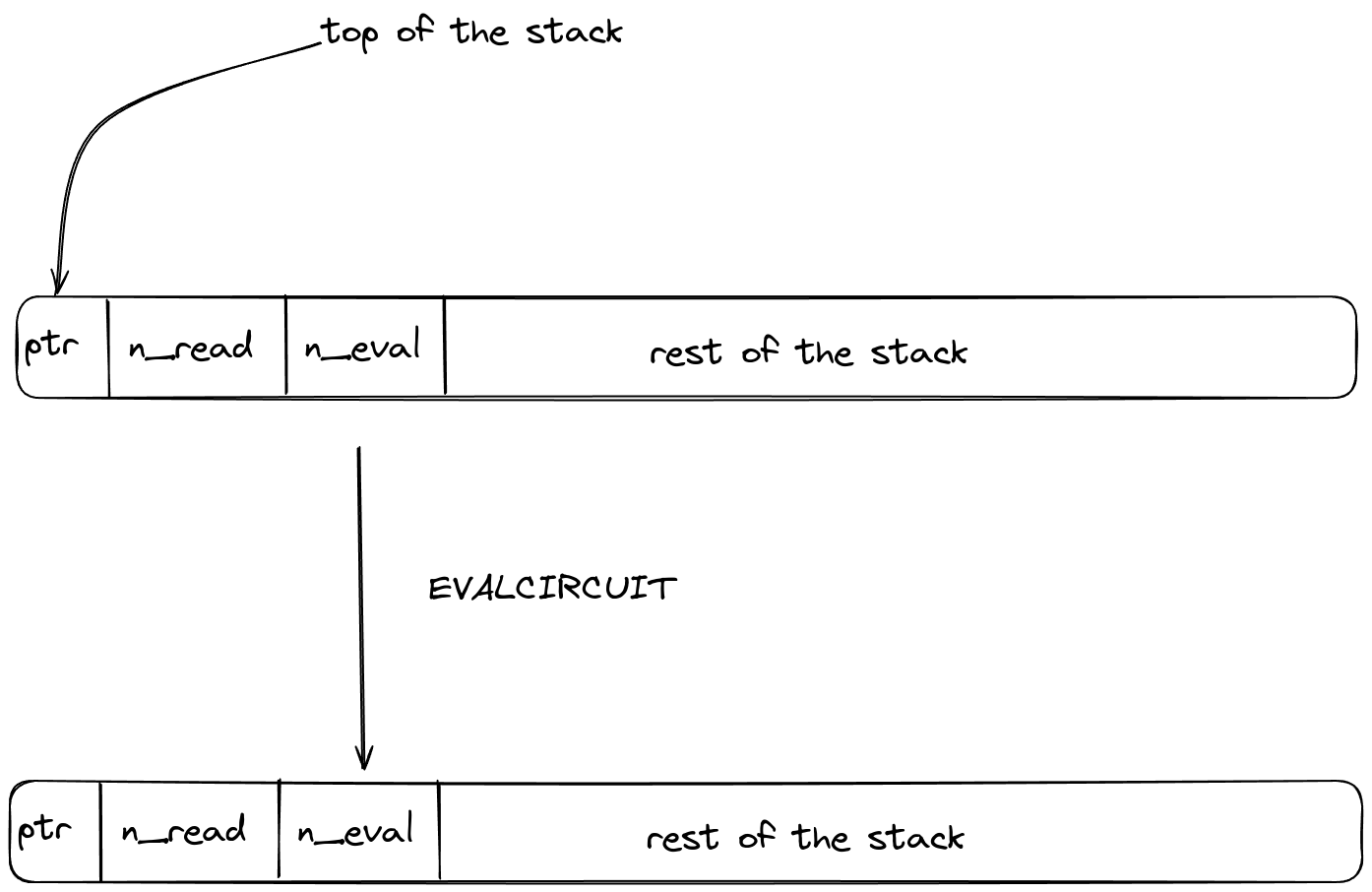
Calling the operation has no effect on the stack or on helper registers. Instead, it removes one
typed AceInit message with multiplicity :
where:
- is the memory context from which the operation was initiated,
- is the clock cycle at which the operation was initiated,
- , and are as above.
The ACE chiplet adds the matching message with multiplicity .
LOG_DEFERRED
The log_deferred operation folds a verified statement digest STMNT into the rolling deferred
root. The update is the structural digest of Node::and(ROOT_PREV, STMNT), computed as one Eidos
compression using the fixed chaining value derived from the registered deferred-AND domain:
ROOT_NEW = Eidos::compress(DEFERRED_AND_INIT_CV, ROOT_PREV || STMNT). The VM STARK
authenticates the final root as one public value.
Operation Overview
The stack is expected to be arranged as [STMNT, ...]. STMNT must already be present in the
processor's deferred state and evaluate to TRUE; otherwise execution fails when the opcode
attempts to log it. Core-library and precompile support code wrap this low-level opcode by
registering nodes and logging statement digests.
Additionally, the processor maintains a persistent rolling deferred root that is updated with each
LOG_DEFERRED invocation. The previous root is provided non‑deterministically via helper
registers and is denoted ROOT_PREV. The hasher bus links the constrained Eidos compression to
the stack transition, while the deferred state enforces that the logged statement evaluates to
TRUE.
The operation has the following stack transition:
Before:  [STMNT,    ...]
After:   [ROOT_NEW, ...]
The top word is replaced with ROOT_NEW; the remaining stack is preserved. Wrappers usually drop
ROOT_NEW after the opcode.
The operation uses the following helper registers:
- : Hasher chiplet row address
- : Previous deferred root
ROOT_PREV
Note: helper registers expose ROOT_PREV for bus constraints only; the VM maintains the deferred
root internally between invocations.
Bus Communication
Hasher chiplet
The following two messages are sent to the hasher controller, ensuring the validity of the compression. Let denote the -th stack column at that row (top of stack is ). The elements appearing on the bus are:
The input message reduces the Eidos compression state in the canonical order
[ROOT_PREV, STMNT, DEFERRED_AND_INIT_CV]:
The same one-row controller entry returns the updated chaining word with a typed return message. Denote the stack after the instruction by :
and the response message is
The Core row removes both messages with multiplicity . Matching positive controller messages enforce that they occur on one hasher-controller row backed by the same physical Eidos compression cycle.
Deferred-root Initialization
Inside the VM, the deferred root is tracked by the typed LogDeferredRoot virtual-table relation:
each log_deferred update removes the previous root before inserting the next one.
Let . We denote the messages for removing and inserting the root as
The previous-root message has multiplicity and the new-root message has multiplicity .
The verifier supplies two boundary contributions so the chain has fixed endpoints: it adds the
initial TRUE_DIGEST (the zero word) and removes the final four-felt deferred root committed by
the VM trace.
The boundary messages are therefore
Because this compression uses the domain-derived DEFERRED_AND_INIT_CV and outputs an updated chaining
word directly, that word is the deferred root at every step. The final deferred root is a fixed
four-field-element value committed by VmProof, not a variable-length request transcript.