Cryptographic operations
In this section we describe the AIR constraints for Miden VM cryptographic operations.
Cryptographic operations in Miden VM are performed by the Hash chiplet. Communication between the stack and the hash chiplet is accomplished via the chiplet bus . To make requests to and to read results from the chiplet bus we need to divide its current value by the value representing the request.
Thus, to describe AIR constraints for the cryptographic operations, we need to define how to compute these input and output values within the stack. We do this in the following sections.
HPERM
The HPERM operation applies Rescue Prime Optimized permutation to the top elements of the stack. The stack is assumed to be arranged so that the elements of the rate are at the top of the stack. The capacity word follows, with the number of elements to be hashed at the deepest position in stack. The diagram below illustrates this graphically.
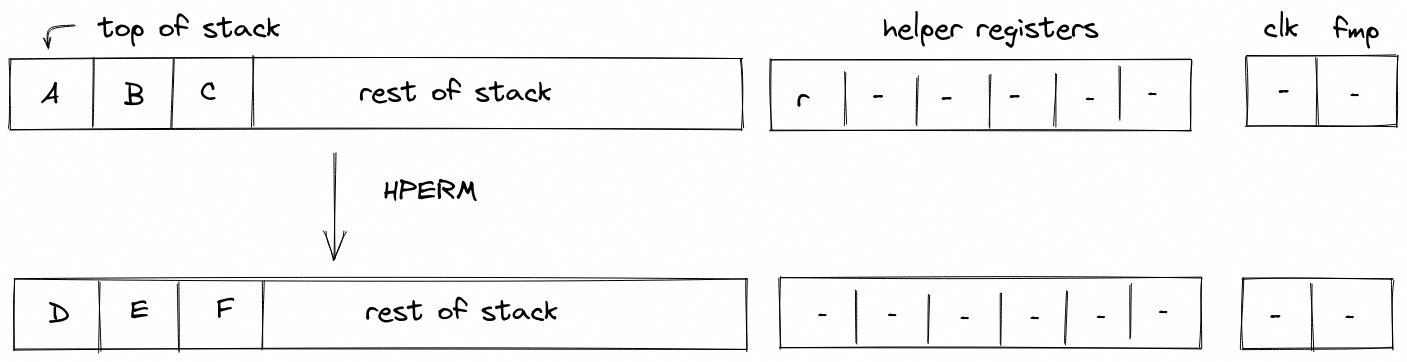
In the above, (located in the helper register ) is the row address from the hash chiplet set by the prover non-deterministically.
For the HPERM operation, we define input and output values as follows:
In the above, and are the unique operation labels for initiating a linear hash and reading the full state of the hasher respectively. Also note that the term for is missing from the above expressions because for Rescue Prime Optimized permutation computation the index column is expected to be set to .
Using the above values, we can describe the constraint for the chiplet bus column as follows:
The above constraint enforces that the specified input and output rows must be present in the trace of the hash chiplet, and that they must be exactly rows apart.
The effect of this operation on the rest of the stack is:
- No change starting from position .
MPVERIFY
The MPVERIFY operation verifies that a Merkle path from the specified node resolves to the specified root. This operation can be used to prove that the prover knows a path in the specified Merkle tree which starts with the specified node.
Prior to the operation, the stack is expected to be arranged as follows (from the top):
- Value of the node, 4 elements ( in the below image)
- Depth of the path, 1 element ( in the below image)
- Index of the node, 1 element ( in the below image)
- Root of the tree, 4 elements ( in the below image)
The Merkle path itself is expected to be provided by the prover non-deterministically (via the advice provider). If the prover is not able to provide the required path, the operation fails. Otherwise, the state of the stack does not change. The diagram below illustrates this graphically.
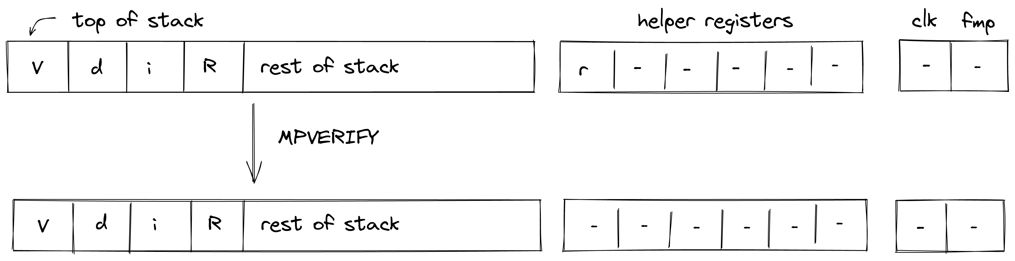
In the above, (located in the helper register ) is the row address from the hash chiplet set by the prover non-deterministically.
For the MPVERIFY operation, we define input and output values as follows:
In the above, and are the unique operation labels for initiating a Merkle path verification computation and reading the hash result respectively. The sum expression for inputs computes the value of the leaf node, while the sum expression for the output computes the value of the tree root.
Using the above values, we can describe the constraint for the chiplet bus column as follows:
The above constraint enforces that the specified input and output rows must be present in the trace of the hash chiplet, and that they must be exactly rows apart, where is the depth of the node.
The effect of this operation on the rest of the stack is:
- No change starting from position .
MRUPDATE
The MRUPDATE operation computes a new root of a Merkle tree where a node at the specified position is updated to the specified value.
The stack is expected to be arranged as follows (from the top):
- old value of the node, 4 element ( in the below image)
- depth of the node, 1 element ( in the below image)
- index of the node, 1 element ( in the below image)
- current root of the tree, 4 elements ( in the below image)
- new value of the node, 4 element ( in the below image)
The Merkle path for the node is expected to be provided by the prover non-deterministically (via merkle sets). At the end of the operation, the old node value is replaced with the new root value computed based on the provided path. Everything else on the stack remains the same. The diagram below illustrates this graphically.
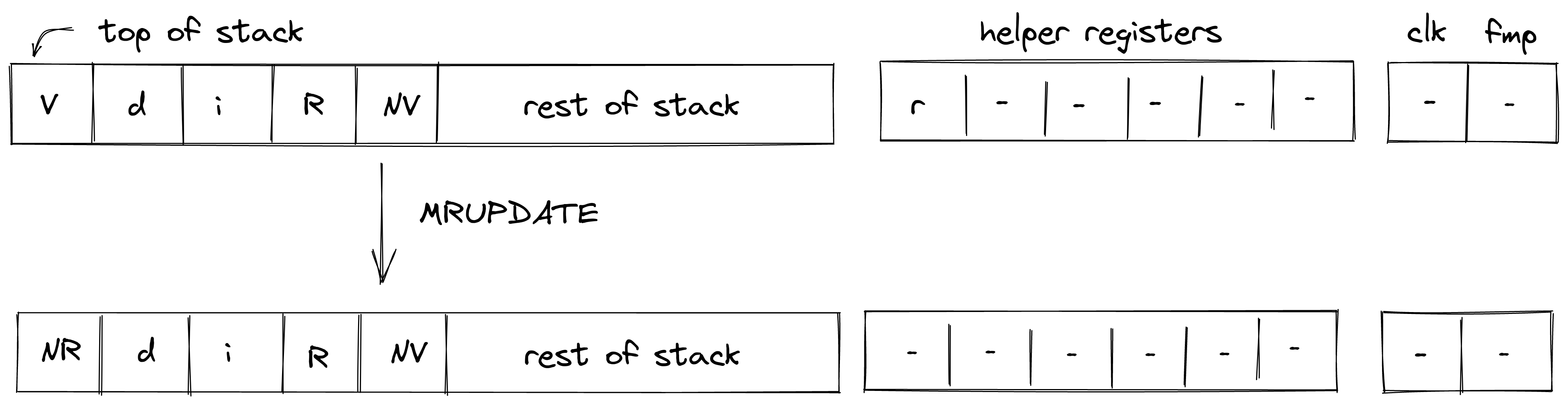
In the above, (located in the helper register ) is the row address from the hash chiplet set by the prover non-deterministically.
For the MRUPDATE operation, we define input and output values as follows:
In the above, the first two expressions correspond to inputs and outputs for verifying the Merkle path between the old node value and the old tree root, while the last two expressions correspond to inputs and outputs for verifying the Merkle path between the new node value and the new tree root. The hash chiplet ensures the same set of sibling nodes are used in both of these computations.
The , , and are the unique operation labels used by the above computations.
The above constraint enforces that the specified input and output rows for both, the old and the new node/root combinations, must be present in the trace of the hash chiplet, and that they must be exactly rows apart, where is the depth of the node. It also ensures that the computation for the old node/root combination is immediately followed by the computation for the new node/root combination.
The effect of this operation on the rest of the stack is:
- No change for positions starting from .
FRIE2F4
The FRIE2F4 operation performs FRI layer folding by a factor of 4 for FRI protocol executed in a degree 2 extension of the base field. It also performs several computations needed for checking correctness of the folding from the previous layer as well as simplifying folding of the next FRI layer.
The stack for the operation is expected to be arranged as follows:
- The first stack elements contain query points to be folded. Each point is represented by two field elements because points to be folded are in the extension field. We denote these points as , , , .
- The next element is the query position in the folded domain. It can be computed as , where is the position in the source domain, and is size of the folded domain.
- The next element is a value indicating domain segment from which the position in the original domain was folded. It can be computed as . Since the size of the source domain is always times bigger than the size of the folded domain, possible domain segment values can be , , , or .
- The next element is a power of initial domain generator which aids in a computation of the domain point .
- The next two elements contain the result of the previous layer folding - a single element in the extension field denoted as .
- The next two elements specify a random verifier challenge for the current layer defined as .
- The last element on the top of the stack () is expected to be a memory address of the layer currently being folded.
The diagram below illustrates stack transition for FRIE2F4 operation.

At the high-level, the operation does the following:
- Computes the domain value based on values of and .
- Using and , folds the query values into a single value .
- Compares the previously folded value to the appropriate value of to verify that the folding of the previous layer was done correctly.
- Computes the new value of as (this is done in two steps to keep the constraint degree low).
- Increments the layer address pointer by .
- Shifts the stack by to the left. This moves an element from the stack overflow table into the last position on the stack top.
To keep the degree of the constraints low, a number of intermediate values are used. Specifically, the operation relies on all helper registers, and also uses the first elements of the stack at the next state for degree reduction purposes. Thus, once the operation has been executed, the top elements of the stack can be considered to be "garbage".
TODO: add detailed constraint descriptions. See discussion here.
The effect on the rest of the stack is:
- Left shift starting from position .
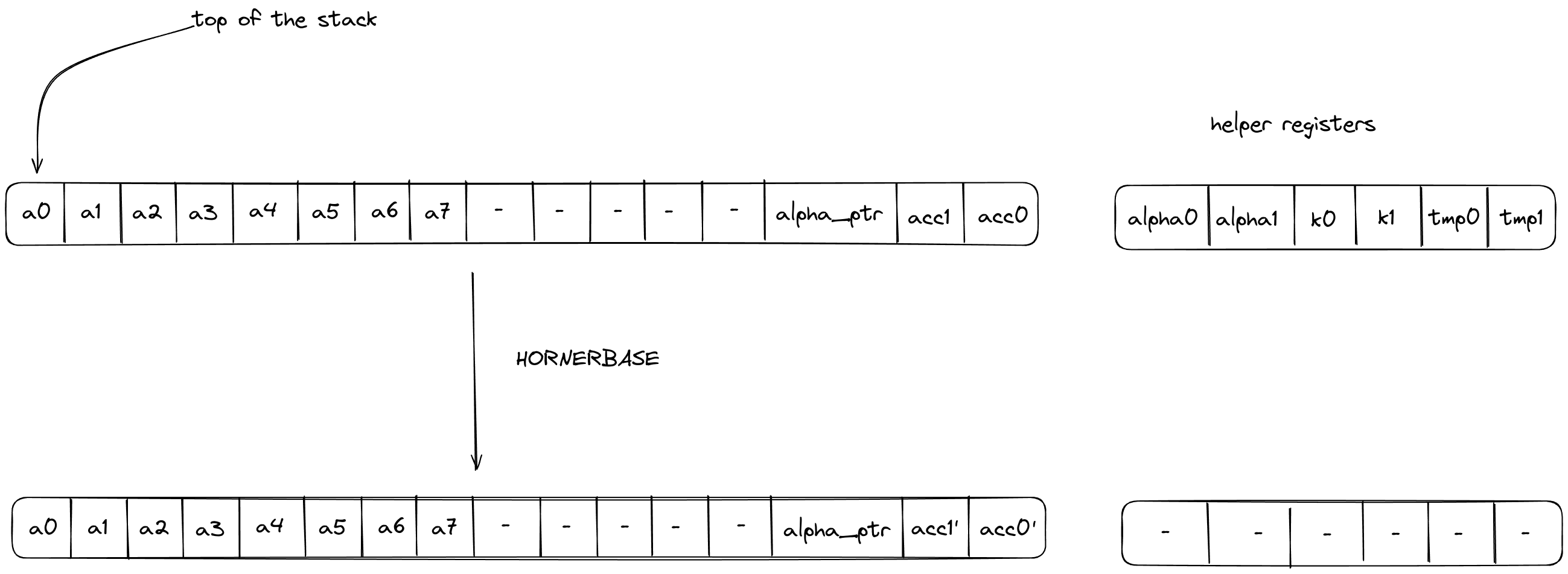
HORNERBASE
The HORNERBASE operation performs steps of the Horner method for evaluating a polynomial with coefficients over the base field at a point in the quadratic extension field. More precisely, it performs the following update to the accumulator on the stack
where are the coefficients of the polynomial, the evaluation point, the current accumulator value, the updated accumulator value, and is a helper variable used for constraint degree reduction.
The stack for the operation is expected to be arranged as follows:
- The first stack elements are the base field elements representing the current 8-element batch of coefficients for the polynomial being evaluated.
- The next stack elements are irrelevant for the operation and unaffected by it.
- The next stack element contains the value of the memory pointer
alpha_ptrto the evaluation point . The word address containing is expected to have layout where is the second half of the memory word containing . Note that, in the context of the above expressions, we only care about the first half i.e., , but providing the second half of the word in order to be able to do a one word memory read is more optimal than doing two element memory reads. - The next stack elements contain the value of the current accumulator .
The diagram below illustrates the stack transition for HORNERBASE operation.
After calling the operation:
- Helper registers will contain the values .
- Stack elements and will contain the value of the updated accumulator i.e., .
More specifically, the stack transition for this operation must satisfy the following constraints:
The effect on the rest of the stack is:
- No change.
The HORNERBASE makes one memory access request:
HORNEREXT
The HORNEREXT operation performs steps of the Horner method for evaluating a polynomial with coefficients over the quadratic extension field at a point in the quadratic extension field. More precisely, it performs the following update to the accumulator on the stack
where are the coefficients of the polynomial, the evaluation point, the current accumulator value, the updated accumulator value, and is a helper variable used for constraint degree reduction.
The stack for the operation is expected to be arranged as follows:
- The first stack elements contain base field elements that make up the current 4-element batch of coefficients, in the quadratic extension field, for the polynomial being evaluated.
- The next stack elements are irrelevant for the operation and unaffected by it.
- The next stack element contains the value of the memory pointer
alpha_ptrto the evaluation point . The word address containing is expected to have layout where is the second half of the memory word containing . Note that, in the context of the above expressions, we only care about the first half i.e., , but providing the second half of the word in order to be able to do a one word memory read is more optimal than doing two element memory reads. - The next stack elements contain the value of the current accumulator .
The diagram below illustrates the stack transition for HORNEREXT operation.
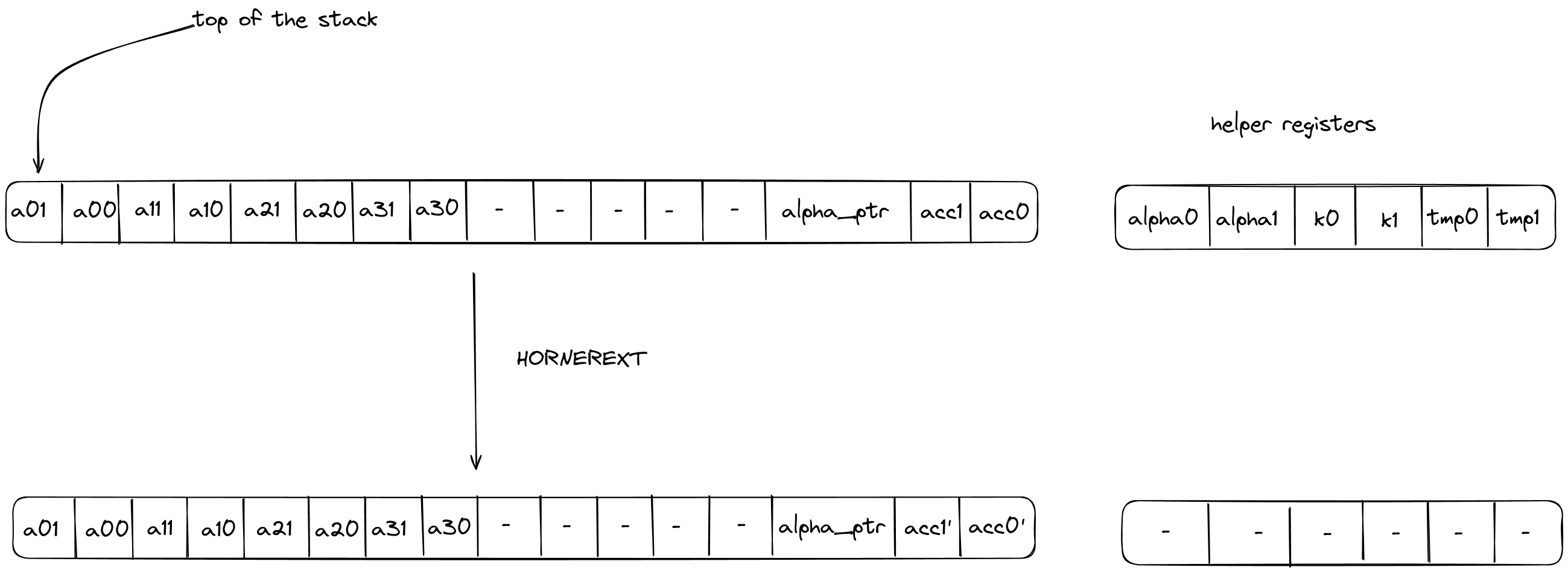
After calling the operation:
- Helper registers will contain the values .
- Stack elements and will contain the value of the updated accumulator i.e., .
More specifically, the stack transition for this operation must satisfy the following constraints:
The effect on the rest of the stack is:
- No change.
The HORNEREXT makes one memory access request:
EVALCIRCUIT
The EVALCIRCUIT operation evaluates an arithmetic circuit, given its circuit description and a set of input values, using the ACE chiplet and asserts that the evaluation is equal to zero.
The stack is expected to be arranged as follows (from the top):
- A pointer to the circuit description with the expected layout by the ACE chiplet.
- The number of quadratic extension field elements that are read during the
READphase of circuit evaluation. - The number of base field elements representing the encodings of instructions that make up the circuit being evaluated during the
EVALphase of circuit evaluation.
The diagram below illustrates this graphically.
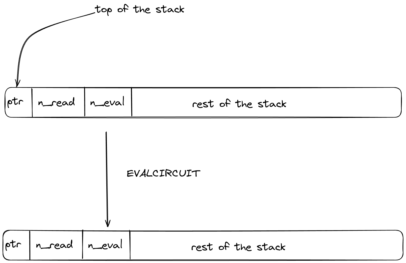
Calling the operation has no effect on the stack or on helper registers. Instead, the operation makes a request to the ACE chiplet using the chiplets' bus. More precisely, let
where:
- is the unique operation labels for initiating a circuit evaluation request to the ACE chiplet,
- is the memory context from which the operation was initiated,
- is the clock cycle at which the operation was initiated,
- , and are as above.
Then, using the above value, we can describe the constraint for the chiplets' bus column as follows:
LOG_PRECOMPILE
The log_precompile operation logs a precompile event by recording two user-provided words (TAG and COMM) into the precompile transcript (implemented via an RPO sponge). Initialization and boundary enforcement are handled via variable‑length public inputs; see Precompile flow for a high‑level overview. This section concentrates on the stack interaction and bus messages.
Operation Overview
The stack is expected to be arranged as [COMM, TAG, PAD, ...]. See Precompiles for a thorough explanation of the precompile commitment model. In brief:
TAGencodes the precompile's event ID (first element) along with metadata or simple outputs (remaining elements),COMMcommits to the precompile inputs (and may include outputs for long results),PADis a word that will get overwritten in the next cycle.
Additionally, the processor maintains a persistent precompile transcript state word CAP (the sponge capacity) that is updated with each LOG_PRECOMPILE invocation. This word is provided non-deterministically via helper registers and is denoted CAP_PREV. The virtual table bus links each removal to a matching insertion, ensuring a single, consistent state sequence.
The operation evaluates [CAP_NEXT, R0, R1] = RPO([CAP_PREV, TAG, COMM]), with the following stack transition
Before:  [COMM, TAG, PAD,      ...]
After:   [R1,   R0,  CAP_NEXT, ...]
The VM updates its internal precompile transcript state (CAP_NEXT) using a bus as we describe below. The rate outputs R0 and R1 are transient; together with CAP_NEXT, they are typically dropped by the caller immediately after logging.
The operation uses the following helper registers:
- : Hasher chiplet row address
- : Previous capacity
CAP_PREV
Note: helper registers expose CAP_PREV for bus constraints only; the VM maintains the
transcript state internally between invocations.
Bus Communication
Hasher chiplet
The following two messages are sent to the hasher chiplet, ensuring the validity of the resulting permutation. Let denote the -th stack column at that row (top of stack is ). The elements appearing on the bus are:
The input message therefore reduces the RPO state in the canonical order [CAP_PREV, TAG, COMM]:
Seven rows later, the op_retstate response provides the permuted state [CAP_{next}, R0, R1]. Denote the stack after the instruction by ; the top twelve elements are [R1, R0, CAP_NEXT] in reverse order. Thus
and the response message is
Using the above values, we can describe the constraint for the chiplet bus column as follows:
The above constraint enforces that the specified input and output rows must be present in the trace of the hash chiplet, and that they must be exactly 7 rows apart. The RPO permutation outputs [CAP, R0, R1]; on the stack, the VM stores these words as [R1, R0, CAP].
Given the similarity with the HPERM opcode which sends the same message, albeit from different variables in the trace, it should be possible to combine the bus constraint in a way that avoids increasing the degree of the overall bus expression.
Capacity Initialization
Inside the VM, the transcript state (sponge capacity) is tracked via the virtual table bus: each update removes the previous entry before inserting the next one.
We denote the messages for removing and inserting the message as
The bus constraint is applied to the virtual table column as follows.
To ensure the column accounts for the initial and final transcript state, the verifier initializes the bus with variable‑length public inputs (see kernel ROM chiplet). More specifically, it constrains the first value of the bus to be equal to
Usually, we initialize the transcript state to the empty word [0,0,0,0], though it may also be used to extend an existing running state from a previous execution. The final transcript state is provided to the verifier (as a variable‑length public input) and enforced via the boundary constraint.
The messages and are given by
The bus records only the transcript state (sponge capacity); the VM never finalizes the digest internally. Instead, the verifier (or any external consumer) reconstructs the transcript from the recorded requests. By convention, when a digest is required, the transcript is finalized by absorbing two empty words and applying one more permutation—matching the fact that log_precompile discards the rate outputs (R0, R1) after each absorption.